After you have all the components blocked out on the canvas, you're ready to start adding wires. Select the wiring tool (third tool in the first group - a line connecting two circles). Then start dragging from one position to another in the canvas area, and wires will start appearing.
It's extremely important to connect the wires to the gates in exactly the right places. The output of the AND gate has to be exactly in the center. (Logisim will actually assume that's what you meant as long as you click close enough.) You can connect however many inputs you can fit (up to five) onto the left side of AND and OR gates.
Some things to remember about the wiring: As you'll quickly discover, Logisim only allows you to draw horizontal and vertical wires. Logisim automatically connects any wires you draw - it'll detect, for example, that it wants to draw those little dots right next to the circuit's inputs.
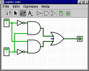
A common error is to overshoot the input to the OR gate. You have to hit the left side of those little legs going into it. You know it's wrong if, after you get everything connected, a green or black wire turns into the blue leg on the OR gate. Notice that in my picture above, only the clearly unconnected OR leg is blue. The other two legs are dark green. That indicates that it's connected.