 RAM
RAM
| Library: |
Memory |
| Introduced: |
2.0 Beta 1 |
| Appearance: |
 |
Behavior
The RAM component, easily the most complex component in Logisim's
built-in libraries, stores up to 4,096 values (specified in the Address
Bit Width attribute), each of which can include up to to 32 bits
(specified in the Data Bit Width attribute). The circuit can load and
store values in RAM. Also, the user can modify individual values
interactively via the Poke Tool, or the user can modify the entire
contents via the Menu Tool.
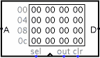
Current values are displayed in the component. Addresses displayed
are listed in gray to the left of the display area. Inside, each value
is listed using hexadecimal. The value at the currently selected address
will be displayed in inverse text (white on black).
Pins
- A on west edge (input, bit width matches Address Bit Width attribute)
- Selects which of the values are currently being accessed by the
circuit.
- D on east edge (input/output, bit width matches Data Bit Width attribute)
- If out is 1 or undefined (i.e, floating), then the RAM
outputs the value at the currently selected address at the D
pin. (A zero on sel with disable this.) If out
is 0, then the D pin is an input, as a value that will be placed at the
currently selected address once the clock rises from 0 to 1.
- sel on south edge (input, bit width 1)
- If you have just one RAM module, ignore this input.
If you have multiple RAM modules in parallel, you can use this input
to enable or disable the entire RAM module, based on whether the value is
1 or 0. In other words, when this is 0, no value is emitted on
the D output, and the values in memory will not
change when the clock rises from 0 to 1.
- triangle on south edge (input, bit width 1)
- Clock input: When out is 0, and this input
rises from 0 to 1 (and sel is 1/undefined and
clr is 0), then the value at the currently selected address
changes to whatever value is
at the D pin. As long as the clock input remains 0 or 1,
though, the D value will not be stored into memory.
- out on south edge (input, bit width 1)
- Selects whether the RAM should emit (on D)
the value at the current address (A). This output behavior
is enabled if out is 1 or undefined; if out
is 0, then D behaves as an input for writing a value
once the clock rises from 0 to 1.
- clr on south edge (input, bit width 1)
- When this is 1, and sel is 1 or undefined, all values
in memory are pinned to 0, no matter what the other inputs are.
Attributes
- Address Bit Width
- The bit width of the address bits. The number of values stored in
RAM is 2addrBitWidth.
- Data Bit Width
- The bit width of each individual value in memory.
Poke Tool Behavior
See poking memory
in the User's Guide.
Text Tool Behavior
None.
Menu Tool Behavior
See pop-up menus and files
in the User's Guide.
Back to Library Reference