- Logisim home page
- Guide to Being a Logisim User
- Library Reference
Wire colors
We are now in a position to summarize the full rainbow of colors that Logisim wires can take on. The following little circuit illustrates all of them at once.
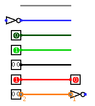
Gray: The wire's bit width is unknown. This occurs because the wire is not attached to any components' inputs and outputs. (All inputs and outputs have a defined bit width.)
Blue: The wire is for carrying a one-bit value, but the value it is carrying is not known. In the above example, this is occurring because the NOT gate's input is unknown, and so its output is also unknown.
Dark green: The wire is carrying a one-bit 0 value.
Bright green: The wire is carrying a one-bit 1 value.
Black: The wire is carrying a multi-bit value. Some or all of the bits may not be specified.
Red: The wire is carrying an error value. This usually arises because conflicting values on the wire. (The other possibility would be that a library component is programmed to emit an error value for another reason; in the built-in libraries, though, error values arise only from propagating other error values.) In the above example, we have one input pin placing a 0 on the wire and another placing a 1 on the wire, causing a conflict. Multi-bit wires will turn red when any of the bits carried are error values.
Orange: The components attached to the wire do not agree in bit width. An orange wire is effectively "broken": It does not carry values between components.
Next: User's Guide.